Carburation – The Manchester XPAG Tests
Reproduction in whole or in part of any article published on this website is prohibited without written permission of The MG Car Club.
By Paul Ireland
Introduction
This article looks at how the SU carburettor works and how it can be adjusted to improve the combustion process, helping to reduce under-bonnet temperatures.
Reproduced with the author’s permission from the book Skinner’s Union published by The S.U. Carburetter Company. Ltd.
SU Carburettor
If you own an unmodified, classic MG it will probably be fitted with one or more SU carburettors. These are a marvel of engineering. Originally designed by George Herbert (Bert) Skinner and made by his younger brother Thomas Carlyle (Carl) Skinner, the SU carburettor was first produced in 1908. Unchanged in the way they operated, SU carburettors were fitted to production cars until 1993.
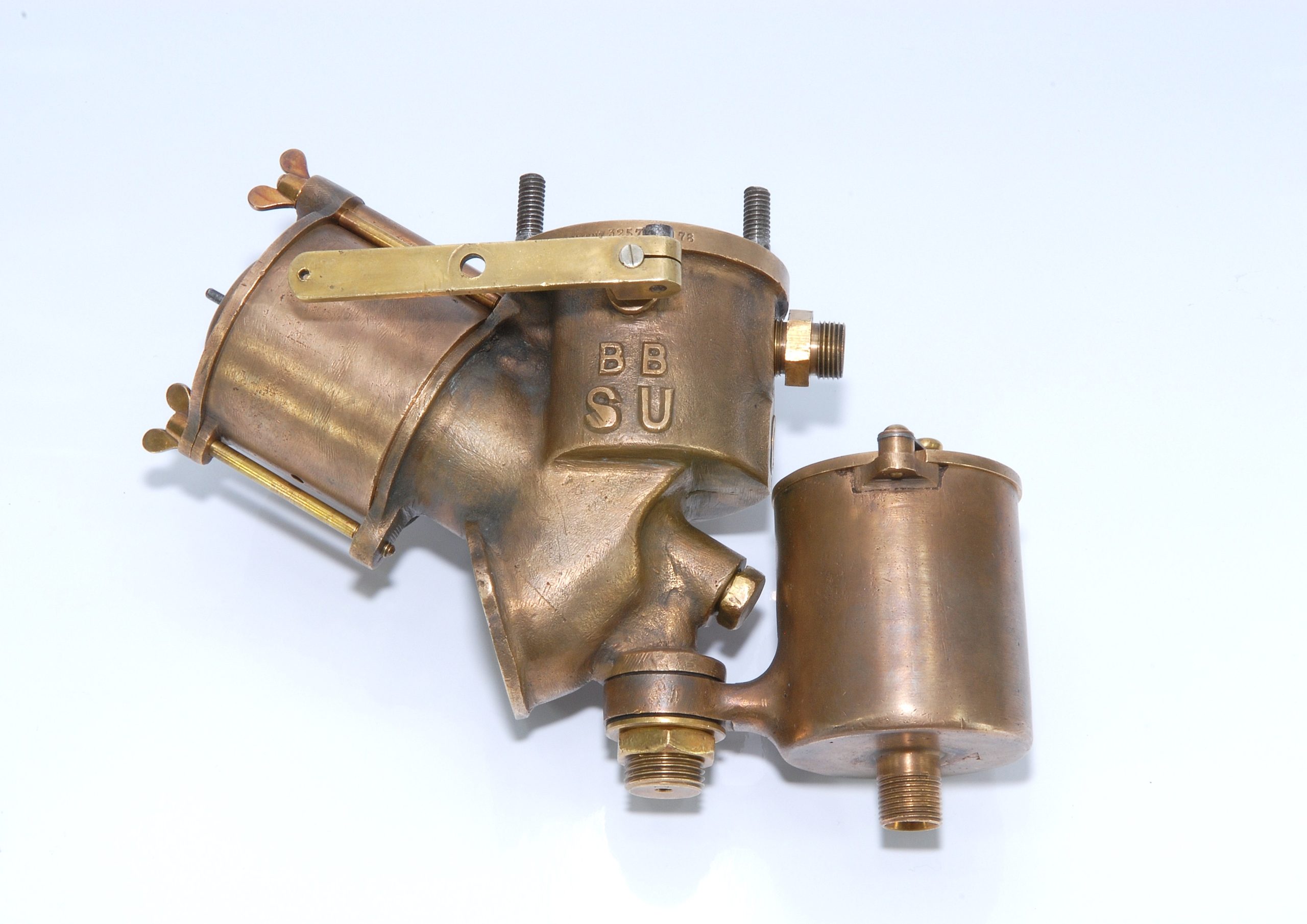
The original SU carburettor had the connection to the inlet manifold at the top with a sloping suction chamber; the carburettors fitted to MGs have the connection on the side with a vertical suction chamber. Apart from this difference, both the suction chamber on the left and the float chamber on the right are clearly recognisable on this original SU carburettor.
In operation, the SU measures the volume of air flowing into the engine and mixes this with a metered volume of finely atomised petrol droplets to give a precise Air to Fuel Ratio (AFR) for all throttle settings and engine revs.
With non-ethanol blended petrol the theoretical AFR is 14.7:1 i.e. for every 1 gm of petrol you need 14.7 gm of air for all the hydrogen atoms to burn to produce water (H20) and all the carbon atoms to burn to produce carbon dioxide (CO2). However, maximum power is achieved with an AFR of between 12.5:1 and 13.5:1, having an excess of petrol or a mixture that is richer than the ideal. This is because some of the carbon burns to carbon monoxide (CO) using only one oxygen atom rather than the two needed when it burns to carbon dioxide (CO2). Normally people talk about LAMBDA. This is the ratio of the AFR an engine is producing divided by the theoretical ideal. Numbers less than 1 correspond to a rich mixture and greater than 1 a weak mixture.
The SU maintains an accurate Lambda between 0.85 (richer) and 0.95 (maximum power) over a very large range of air flow rates from tick over, when virtually no air is flowing, to full throttle at 5000rpm or more, when some three cubic metres of air are flowing through it every minute. However, an observant reader will note the SU carburettor is a volumetric device: it measures the volume of air and petrol; AFR is defined in terms of mass. The volume of a given mass of petrol or air depends on its density. While the density of petrol changes very little under normal operating conditions, the density of air can vary with ambient temperature, barometric air pressure or altitude. Fortunately, the SU is also relatively insensitive to changes in air temperature and air pressure, allowing our cars to work in the winter and hot summers, at sea level and when driving over the top of alpine passes.
What is amazing, it achieves all this with only one moving part!
Unfortunately, for many, the SU carburettor is something to be left untouched. Once set up, it will continue to work for many miles, but it does benefit from regular maintenance. Also, changes in modern fuel mean that they may now require re-tuning in order to achieve optimum performance.
Investigating how modern petrol affected the operation of the SU carburettor was one of the objectives of the Manchester XPAG tests.
How does an SU Carburettor work?
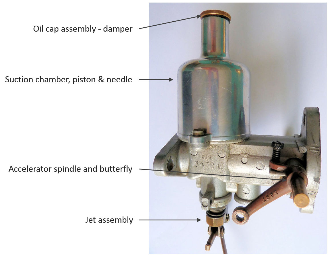 The main function of the SU, measuring the air flow, is achieved by a piston fitted inside the suction chamber.
Sitting on top of the carburettor body, the suction chamber is the most recognisable characteristic of an SU carburettor. The major difference between a modern SU and the original shown above is that the original SUs, used leather bellows instead of a piston. Around 1914, improved engineering allowed the leather bellows to be replaced with a close-fitting suction piston.
The carburettor body can be thought of as consisting of four different areas (P1 to P4, see the diagram)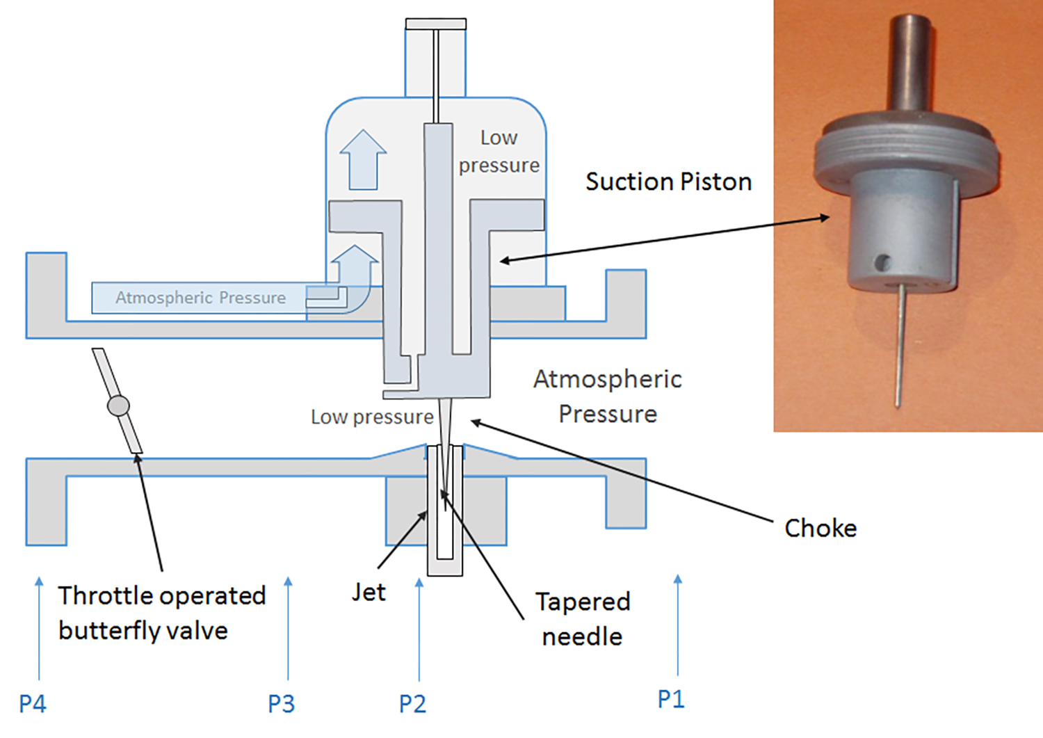
- P1 – where the air flows into the carburettor. This is at atmospheric pressure.
- P2 – the area below the suction piston is called the choke. Here the air is at a lower pressure than atmospheric.
- P3 – the area beyond the piston and before the throttle. This contains an area called the Vena Contracta, a recovery zone around the rear of the piston where the air pressure returns to atmospheric.
- P4 – the area beyond the throttle butterfly. On small throttle settings the pressure in this area can be a near vacuum, especially at high engine revs, increasing to virtually atmospheric pressure when the throttle is wide open.
The bottom of the suction piston partially blocks, or chokes, the airflow into the engine causing the air to travel faster through the choke, reducing its pressure. As a result, the air pressure inside the choke is lower than atmospheric. In practice, this low pressure area extends up and around the rear of this piston in the Vena Contracta.
Without any seals that could cause friction, the top of the piston is a close fit inside the suction chamber and is free to move up and down. The bottom of the suction chamber is open to atmospheric pressure and there is a drilling through the suction piston, either at the bottom rear or underneath, connecting the low pressure area of the choke to the top of the suction chamber. When the engine is running, there is a pressure difference between the top and bottom of the piston which causes it to move upwards.
As the piston moves up, the choking effect is reduced, allowing air to flow more slowly. This in turn reduces the pressure difference between the top and bottom of the suction piston. If the piston moves up too far, the pressure difference cannot support its weight and it falls, increasing the speed of the air flow and the pressure difference. As a result the piston settles at a height where the pressure difference between atmospheric and that in the choke equates to the weight of the piston. A constant pressure difference is maintained regardless of the volume of air flowing into the carburettor, hence the reason the SU carburettor is sometimes called a constant pressure device. In practice, the height of the piston is a direct measure of the volume of air flowing through the carburettor.
Strictly, this statement is not true. On early (pre 1950s) carburettors, the piston was made of bronze or brass weighing about 8.5oz; later carburettors (as shown above) had aluminium pistons with a steel insert to give the same weight. In these carburettors the downward force is fixed and independent of the height of the piston. These really are constant pressure devices.
In the 1950s, the heavier pistons were replaced with lighter aluminium pistons with a long spring fitted to increase the downward force to around 8.5oz. As the throttle is opened and the piston rises the spring is compressed increasing the downward force. A greater pressure difference is needed to support this increased downward force which, in turn, reduces the area of the choke relative to a fixed weight piston. The implications of this are discussed in the next article.
Connected to the bottom of the piston is a tapered needle that fits into a fixed diameter jet. The jet is filled with petrol to a set level, controlled by a float and needle valve in the float chamber. The float chamber is open to atmospheric pressure via the breather tube and the pressure in the choke is lower than atmospheric, causing the petrol to ‘squirt’ out of the jet into the choke. The volume of petrol is controlled by the pressure difference and the annulus between the tapered needle and jet. The taper on the needle is such that the correct volume of petrol enters the choke for every piston height or volume of air flowing though the carburettor. Petrol leaving the jet enters the high velocity air stream in the choke, breaking into droplets and dispersing as it travels through the carburettor.
This is how the SU carburettor delivers an accurately metered volume of finely atomised petrol droplets into the inflowing air to maintain the correct air/fuel ratio.
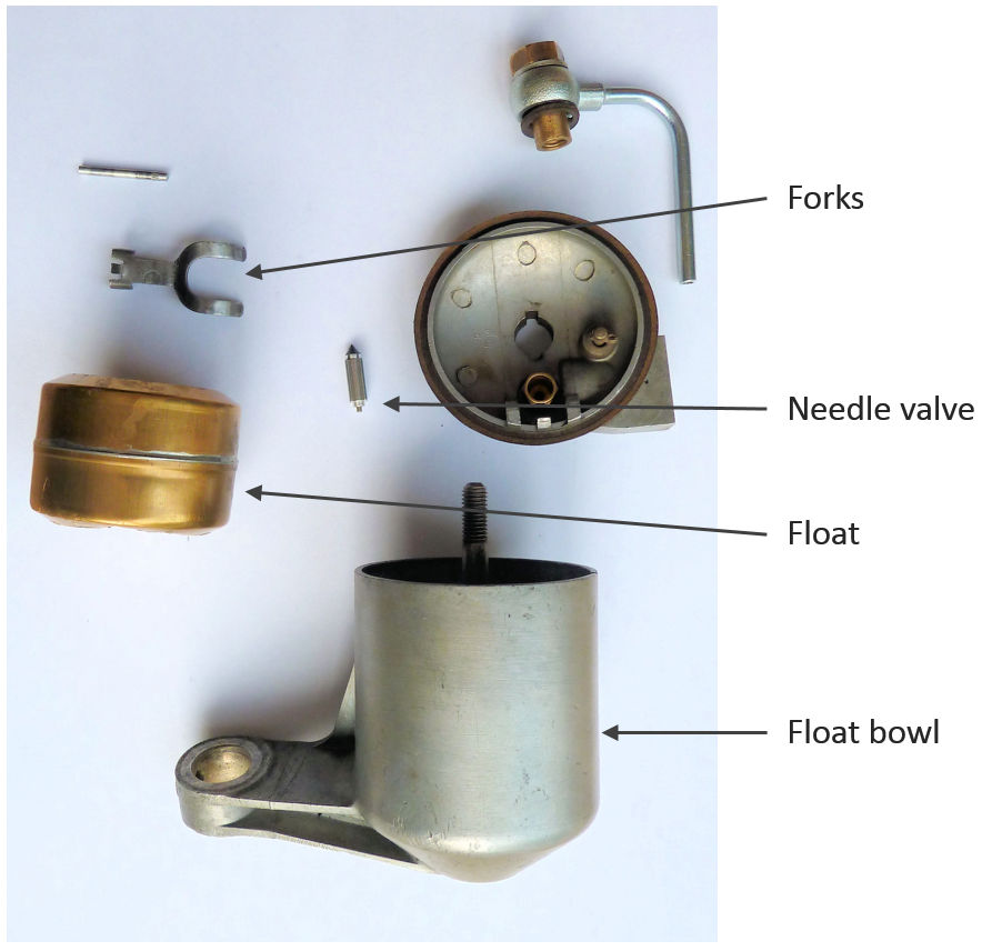
Damper and Float Chamber
The two other auxiliary parts that make up the SU carburettor are the damper and float chamber.
The guide rod in the centre of the piston is hollow. From about 1947, MGs were fitted with a damper connected to the screw cap at the top of the suction chamber. This served two purposes.
Firstly, it slowed the rate the suction piston could rise when the throttle was quickly depressed, temporarily enrichening the mixture to improve acceleration. Secondly, it helped stop the piston vibrating due to rapid pressure changes in the manifold when the inlet valve opens.
 It is important the oil in the hollow piston guide rod is checked and topped up if necessary. The oil should be filled to a level just below the top of the hollow piston rod. A slight excess will overflow the top of the hollow rod and lubricate the guide. However, overfilling the damper will cause the excess oil to be sucked into the suction chamber and onto its walls, which can cause the suction piston to stick.
The sole purpose of the float chamber is to keep the petrol level in the jet constant. As the fuel level drops, the float also drops allowing the needle valve to open and more petrol to flow into the float chamber.
Tuning SU Carburettors
There are a number of adjustments that can be made to an SU carburettor to optimise performance. Traditionally, the aim is to increase power output by delivering the maximum volume of the optimum air/fuel ratio into the engine. Techniques include larger bore carburettors, lighter springs in the suction chamber to reduce the choking effect or removing the air filter. However, the tests at Manchester have shown this approach may not give the best overall road performance.
Remember in the Suck, Squeeze, Bang and Blow article how the effects of increased cyclic variability reduced the number of cycles with the optimum power timing? Poor atomisation and vaporisation of the petrol during the induction stroke leads to uneven mixtures around the plug during the critical time it fires, increasing the cyclic variability.
At Manchester a nebulizer was fitted between the carburettor and inlet manifold. This forced the petrol leaving the carburettor to break up into evenly sized droplets approximately 10-20 micrometres in diameter, similar to those delivered by fuel injection systems. Using a branded forecourt 95 octane petrol running at full throttle gave the following percentage change in power output compared to the engine running on the same fuel without the nebulizer.
 Below 3000rpm, the nebulizer improved power output by around 1%, demonstrating the benefits of improved fuel atomisation at these engine speeds. Unfortunately, the nebulizer used for these tests also constricted the airflow into the engine, explaining power reduction at higher rpm.
Race tuned engines run at full throttle and high rpm. Under these conditions there is a large volume of mixture entering the cylinder with high levels of turbulence and compressive heating. It is likely the degree of fuel atomisation is not such a problem. However, when running under 3000rpm with part throttle settings typically used for normal road driving, the degree of fuel atomisation has an effect. For road use, carburettors should be tuned to maximise turbulence and atomisation even at the expense of a slight reduction in full throttle power.
Adjustment
There are only four main ways of adjusting an SU carburettor. Two are relatively easy: adjusting the jet height or fuel level in the jet; the other two require changing the suction piston and spring or the tapered needle. Despite this, it is possible to tune the SU to work with a variety of fuels.
In addition, if your car is fitted with a damper, it may be worth experimenting with different viscosity oils and using one that gives the best acceleration response and smoothest low rev driving.
Changing the Mixture
Jet height
Adjusting the height of the jet has the effect of changing the mixture over the whole rev/throttle range.
On the bottom of the jet assembly of earlier carburettors is the jet stop nut which can be screwed up or down to adjust the jet height. Screwing the nut DOWN increases size of the annulus around the jet and tapered needle, allowing more fuel into the air stream and making the mixture RICHER. Screwing the nut UP makes the mixture WEAKER. On the more modern HIF carburettors there is a mixture-adjusting screw next to the jet assembly that performs the same function.
Tolerances on the needle and jet are very tight and when adjusting the jet height using the nut, only make changes by turning the nut 1 flat or 1/6 turn at a time.
Incidentally, pulling the choke to allow cold starting dramatically lowers the jet, increasing the size of the annulus and making the mixture much richer.
Replacing the tapered needle
The other adjustment to the mixture is performed by replacing the tapered needle. While this is a simple operation, with hundreds of available needles with different tapers, retuning the carburettor is not a simple task. This should be left to the experts. Fitting a needle with a different taper changes the mixture at particular rev range and throttle settings.
There is a very informative book “SU Carburettor Needle Profile Charts” available from Burlen Fuel Systems. This lists all the needles and their profiles. The charts give the needle diameter in 1/8” steps down the needle. A lower diameter gives a richer mixture.
Measuring the required needle diameter under various loads and engine speeds with different fuels was one of the tests performed at Manchester. Sorry to those who race XPAG-engined cars, this data only covers up to 3750 rpm, a typical maximum for road use. This will be covered in the next article.
Maintenance
Once set up, SU carburettors should be maintained; I suggest the following yearly schedule. For cars with twin SUs service one carburettor at a time and do not interchange the parts.
- Remove the suction chamber and clean the inside. I use white spirit. There is no need to oil.
- Clean the suction piston. Be very careful not to bend the needle.
- Replace the suction chamber in the same orientation as it was originally and check the piston rises and drops easily. If you are VERY careful, you can use the damper to lift the suction piston by unscrewing it and moving it to one side and using it to lift the piston. Let it fall. It should drop back with a ‘clunk’. With twin Sus, both pistons should fall at the same rate.
- Ensure the ignition is switched OFF (otherwise you will get petrol everywhere). Remove the float chamber lid and float. Clean out any debris or water from the bottom of the float chamber. This is very important if you are using ethanol blended fuel. Watch out for the later articles.
- Apply a little light oil to the throttle spindles.
Conclusion
The SU carburettor is a marvel of engineering and, if properly maintained, will give many years of service. The tests at Manchester suggest there are minor tweaks that will improve the way the engine runs on modern petrol and have identified two areas where problems occur.